Development of a Method for Rapid and Precise Measurement of Laser Light Helicity
Research Press Release | May 20, 2014
| Press Release | ||
|---|---|---|
| Key Points |
* Measurement of the orbital angular momentum spectrum*2 of ultra-broadband optical vortex pulses*1 in units of seconds. * Permitting evaluation of contamination of an orbital angular momentum component of 1% or less, and wavelength dependency of the orbital angular momentum spectrum. * Application in fields such as multiplexed optical communications*3, precision fabrication, and nonlinear spectroscopy*4 are expected. |
|
| Overview |
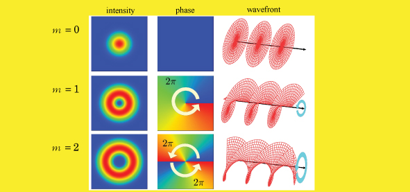
Light having a helical wavefront in the form of a helix is referred to as an ‘optical vortex’, and is the subject of much attention for its applications in such areas as optical tweezers, laser fabrication, optical communications, and quantum information processing. Use of a spiral phase plate*5 or liquid crystal phase modulator*6 permits conversion of laser light to optical vortex laser light (hereafter referred to as an ‘optical vortex’). During this conversion, components of varying degrees of helicity may become mixed for a number of reasons, and precise measurement of such helicity components (the orbital angular momentum spectrum) is essential in applications such as optical communications and quantum information processing*7. While methods of determining the degree of precision of these optical vortices relative to the design exist, they require considerable time for measurement, and are unsuited to measurement of helicity of optical vortices comprising a range of wavelength components. A research group at the Hokkaido University Graduate School of Engineering consisting of Professors Ryuji Morita and Yasunori Toda, and research assistant Keisaku Yamane (associate professor) have developed a method of measuring precisely and rapidly the orbital angular momentum spectrum showing the helicity component distribution using the interference image of an optical vortex and a normal planar wavefront, and applied it to ultra-broadband ultra-short optical vortices with a 600 – 950nm wavelength. This method has been successful in precise measurement of the helicity distribution of wavelength-resolved optical vortices. This method is also applicable to combined optical vortices*8, and has achieved a world-first in successful measurement of phase differences between differing helicity components*9. This success has allowed rapid and precise measurement of helicity distribution in applications such as multiplexed optical communications, quantum information processing, and laser fabrication using optical vortices in which multiple helicities are combined, and much is expected of the method in optimizing design in optical information processing and laser fabrication. The success of this research was made possible through the assistance of the following: * Japan Science and Technology Agency (JST) Strategic Basic Research Programs CREST research area ‘Enhancing Applications of Innovative Optical Science and Technologies by Making Ultimate Use of Advanced Light Sources’ (research supervisor: Professor Tadashi Ito, Osaka University). Research topic: ‘Material control by topological light-waves with total angular momentum’ (research representative: Professor Takashige Omatsu, Chiba University). * The Japan Society for the Promotion of Science, Grants-in-Aid for Scientific Research. |
|
| Explanation of Terms |
*1 Optical vortex/optical vortex pulse Light normally has a planar or near-spherical wavefront (a curved surface for which phase is equal), however light with a helical wavefront is referred to as an ‘optical vortex’. An optical vortex pulse is one in which an optical vortex is emitted periodically. Reducing the duration of pulses increases the bandwidth in the wavelength domain, and results in an ultra-broadband optical vortex pulse. *2 Orbital angular momentum/orbital angular momentum spectrum Light has momentum in the direction perpendicular to the wavefront, and an optical vortex with a helical wavefront has ‘a force revolving around the axis in the direction of travel of the light’. The orbital angular momentum corresponds to this force. The orbital angular momentum of a single photon is given by mħ (ħ: Planck’s constant/2π, m: an integer value), and can take an infinite number of values. When orbital angular momentum differs, the number of turns in the helix of a wavelength, or its orientation, also differs. Measurement of the orbital angular momentum therefore corresponds to measurement of the helicity of the light. When light is resolved into the orbital angular momentum (helicity) components, the orbital angular momentum spectrum corresponds to the light intensity of each component. *3 Multiplexed optical communications A method of optical communications in which light of differing modes is propagated, primarily in optical fiber. Multiplexing permits an increase in transmission capacity. While wavelength multiplexing is most common, here it refers to spatial multiplexing in which modes with differing orbital angular momentums are propagated in a multiplexed manner. *4 Nonlinear spectroscopy A method in which an interaction dependent on the square or cube etc. of an optical-electric field is induced in matter and its properties measured. *5 Spiral phase plate An optical device in which thickness around the central axis changes along a helix. When thickness relative to rotation around the central axis changes only by mλ (λ: wavelength of light), an optical vortex having the orbital angular momentum mħ is created. *6 Liquid crystal phase modulator A device comprised of liquid crystal pixels disposed in two-dimensions and able to change phase with application of a voltage. An optical vortex is generated when a pattern of interference between a planar wavefront and an optical vortex is drawn on this liquid crystal phase modulator illuminated with a planar wavefront. *7 Quantum information processing The manipulation of information for which state is determined based on quantum mechanics. With normal light, polarized light assumes two independent quantum states (e.g. clockwise or counterclockwise circularly polarized light). With optical vortices, despite the same polarization, the difference in orbital angular momentum provides an unlimited number of independent quantum states. *8 Combined optical vortices Optical vortices comprising multiple orbital angular momentum components of comparable intensity. For example, the right-half of the normal donut-shape optical vortex is referred to as a ‘combined optical vortex’. *9 Phase difference Since an optical-electric field can also be described as a wave, it has both amplitude and phase. The square of the amplitude is proportional to the light intensity. Amplitude determines the size of the peaks and troughs of the optical-electric field wave. The phase difference between differing electric fields of differing orbital angular momentum components is referred to here as the ‘phase difference’. |
|
| Inquiries |
Ryuji Morita, Professor, Laboratory of Nonlinear Optics and Laser Physics, Dept. of Applied Physics, Faculty of Engineering, Hokkaido University TEL & FAX: +81-11-706-6626 E-mail: morita@eng.hokudai.ac.jp |
|
|
Japanese Link |
||
| Publications | New Journal of Physics (2014.5.7) | |